Telemecanique XUB0BPSNM12 Photoelectric Sensor: Multimode Performance and Wiring Context
The Telemecanique XUB0BPSNM12 photoelectric sensor is designed for multi-application detection where one reference can support different optical modes depending on the setup. In automation programs that aim to reduce SKU complexity, a multimode photoelectric sensor is often selected to cover a broader range of use cases—such as diffuse sensing, diffuse with background suppression, thru-beam with accessory, or polarised reflex with reflector—while keeping electrical standards consistent.
Product definition
The Telemecanique XUB0BPSNM12 photoelectric sensor is specified within the Photoelectric sensors XU/XUB family as a multimode unit with Sn 0…20 m, operating on 12…24 VDC, using an M12 connection, and employing PNP discrete output architecture. The manufacturer documentation highlights environmental robustness including IP65, IP67, and IP69K ratings.
Key technical characteristics
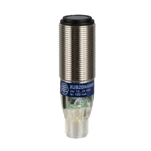
- Brand + code + type: Telemecanique XUB0BPSNM12 photoelectric sensor
- Sensor design: Cylindrical M18 platform (XUB family)
- Detection system: Multimode
- Sensing distance: Sn 0…20 m
- Supply: 12…24 VDC
- Connection: M12
- Protection: IP65 / IP67 / IP69K (double insulation noted in sources)
Multimode optics: why it matters operationally
Multimode capability changes how engineering teams plan deployments. With the Telemecanique XUB0BPSNM12 photoelectric sensor, the same sensor body can be configured for different detection strategies, which can be useful when a line evolves over time. For example, early-stage commissioning might use a reflective mode for quick setup, then shift to background suppression or thru-beam configuration if the process becomes sensitive to reflective variability. The manufacturer documentation references multiple infrared detection modes in the datasheet overview, reinforcing its multi-use nature.
Electrical and diagnostic signals
In field maintenance, diagnostics are not an afterthought. The product reference indicates multiple LEDs: green for supply, red for instability, and yellow for output state, which supports faster on-site verification before deeper troubleshooting. When your goal is stable uptime, these LEDs can reduce time-to-diagnosis by confirming whether the sensor sees instability (alignment, contamination, or optical noise) versus a straightforward output state change.
Environmental robustness and washdown relevance
Protection ratings are not merely labels; they guide where a sensor can be deployed without constant enclosure engineering. The Telemecanique XUB0BPSNM12 photoelectric sensor is associated with IP65/IP67/IP69K ratings in the product reference context. That typically aligns with applications where washdown, spray, or aggressive cleaning cycles are present, provided cabling and connector sealing are implemented correctly.
Integration best practices
- Document the optical mode chosen at the station level to avoid “same sensor, different behavior” confusion.
- Use instability indication (red LED) as a trigger for preventative cleaning or alignment checks.
- Standardize M12 cordsets and ensure sealing practices match the IP intent.
- Tag the I/O point explicitly as Telemecanique XUB0BPSNM12 photoelectric sensor to keep spares governance accurate.
For broader cross-reference and selection alignment across the portfolio, see Telemecanique sensor resources.
FAQ
- What does “multimode” mean for the Telemecanique XUB0BPSNM12 photoelectric sensor?
It indicates the sensor supports multiple optical detection modes such as diffuse and other configurations described in the documentation. - What is the sensing distance?
Sn is listed as 0…20 m. - What supply range is supported?
The sensor is specified for 12…24 VDC. - Which connector format is used?
M12 is indicated for this model. - Why is an instability LED valuable?
It helps separate alignment/optical noise issues from normal output switching, speeding diagnostics.