Telemecanique XS9C2A2A1M12 Inductive Proximity Sensor: Analog 0–10 V Distance Output
The Telemecanique XS9C2A2A1M12 inductive proximity sensor is designed for applications that need more than a simple ON/OFF signal. Instead of discrete switching, this model provides an analog 0…10 V output that can be used for distance-related monitoring, setpoint control, or quality-oriented detection where trends matter.
What this sensor is
The Telemecanique XS9C2A2A1M12 inductive proximity sensor is an XS9 form factor device with a 40 × 40 × 70 body in a PBT enclosure. It is specified as non-flush mountable and uses an M12 4-pin connector for standardized industrial connectivity.
Technical specifications
- Brand + code + type: Telemecanique XS9C2A2A1M12 inductive proximity sensor
- Housing: Form 40 × 40 × 70, PBT
- Mounting: Non-flush mountable
- Nominal sensing distance (Sn): 25 mm
- Signal type: Analogue
- Analogue output range: 0…10 V
- Wiring technique: 3-wire
- Supply: 24 V DC (with reverse polarity protection)
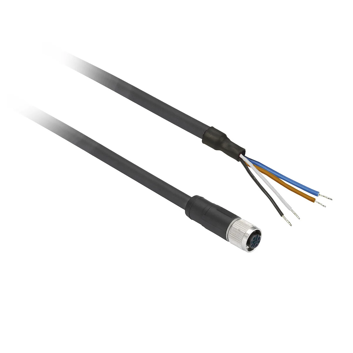
- Connection: M12 male connector, 4 pins
- Protection: IP67, IP65, and IP69K
Why choose analog instead of discrete?
Discrete sensors excel at clear presence confirmation. Analog sensors enable process insight. With the Telemecanique XS9C2A2A1M12 inductive proximity sensor, a controller can interpret the output as a continuous value across the operating zone, enabling:
- Distance-related control decisions (within the sensor’s defined range)
- Monitoring wear or drift by trending analog values over time
- Detecting “too close / too far” conditions without a second sensor
Non-flush mounting and field stability
Non-flush mounting is particularly important for analog proximity sensing because nearby metal can influence the field and therefore the output curve. The Telemecanique XS9C2A2A1M12 inductive proximity sensor should be installed with clearance from surrounding metal structures so the analog signal remains repeatable. If you notice unexpected signal offsets after mechanical modifications, re-check the sensor’s local metal environment first.
Integration notes for controls teams
When connecting analog outputs, the control system configuration is as important as wiring. Confirm the PLC analog input is configured for 0–10 V, verify reference/common wiring practices, and document scaling so maintenance teams can interpret the numbers. In asset records, store the full identifier—Telemecanique XS9C2A2A1M12 proximity sensor—because analog variants are not interchangeable with discrete ones.
Where it fits best
- Gap monitoring where a metal target approaches within a controlled band
- Quality checks based on position consistency
- Condition monitoring where drift indicates mechanical wear
- Automation sequences requiring an analog threshold rather than a hard switch
Operational checks
For stable readings, keep the target surface consistent and avoid installing the sensor near large moving metal masses that can change the field during machine motion. If the analog value is noisy, review cable routing and grounding strategy, and confirm the PLC input filter settings align with the process dynamics.
For additional family context and selection alignment, consult Telemecanique sensor references to standardize outputs, connectors, and protection levels across projects.
FAQ
- Does the Telemecanique XS9C2A2A1M12 inductive proximity sensor provide an analog output?
Yes. It provides an analog 0…10 V output signal. - What is the nominal sensing distance?
It is specified with Sn 25 mm. - What supply voltage is required?
It is rated for 24 V DC operation with reverse polarity protection. - What connector does it use?
It uses an M12 male 4-pin connector. - Is it flush mountable?
No. It is specified as non-flush mountable.