Telemecanique XMLP001GC21F Electronic Pressure Sensor: 0…1 bar 4–20 mA Measurement for Stable Control Loops
Low-pressure measurement is frequently used to govern utility lines, pneumatic circuits, filtration monitoring, and gentle hydraulic applications where small changes in pressure can indicate blockages, leaks, or process drift. In these environments, stability and repeatable scaling matter more than extreme range. The Telemecanique XMLP001GC21F electronic pressure sensor is specified as a pressure transmitter in the Telemecanique Pressure sensors XM family, delivering a 4–20 mA output designed for robust PLC integration.
This article explains what the Telemecanique XMLP001GC21F electronic pressure sensor is, how its specifications translate into control system choices, and how to implement commissioning and maintenance governance so the measurement remains consistent after replacement or plant modifications.
Technical Identity and Specification Highlights
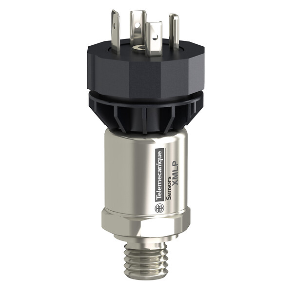
The Telemecanique XMLP001GC21F electronic pressure sensor is specified as a pressure transmitter (XMLP) with a pressure rating of 1 bar and an analogue 4…20 mA output (2-wire technique). It uses a G 1/4A male fluid connection conforming to DIN 3852-E and an electrical connection via a male connector EN 175301-803-A (ex DIN43650), 3 pins. Rated supply voltage is 12…24 V DC SELV with voltage limits of 7…33 V, and current consumption is listed as < 23 mA. IP degree of protection is listed as IP65. Response time on output is specified as ≤ 2 ms (10…90% of full scale), and measurement accuracy is specified as ±0.5% of the measuring range.
- Pressure rating: 1 bar
- Output: 4…20 mA, 2-wire
- Supply: 12…24 V DC SELV (limits 7…33 V)
- Connection: G 1/4A male, DIN-style 3-pin connector
- Performance: ≤2 ms response, ±0.5% accuracy
- Protection: IP65
From an integration standpoint, the 4–20 mA loop is often preferred because it is resilient against electrical noise and voltage drop across longer cable runs. That makes the Telemecanique XMLP001GC21F electronic pressure sensor well suited to distributed measurement points in real plants.
4–20 mA Scaling Governance: Turning Current into Pressure
The reliability of a current-loop transmitter depends on scaling governance in the control system. A typical mapping is:
- 4 mA = 0 bar
- 20 mA = 1 bar
Whatever mapping standard your facility uses, the critical point is to document it and apply it consistently. If scaling changes after a PLC program revision, alarms can shift without any visible wiring change, creating “mysterious” nuisance trips. The Telemecanique XMLP001GC21F electronic pressure sensor should be treated as an instrumented asset with documented scaling, alarm thresholds, and commissioning values.
Media and Temperature Envelope: Practical Fit
Controlled fluid guidance lists fresh water (0…125°C), air (-15…125°C), gas (-15…125°C), and hydraulic oil (-15…125°C). Materials in contact with fluid include fluorocarbon FPM, ceramic, and stainless steel AISI 316L. These characteristics help engineers validate compatibility when pressure points include humid air, utility gas lines, or warm process water. The correct media match reduces drift and protects long-term stability.
Installation Discipline: Mechanical and Electrical Consistency
Low-pressure measurement can be distorted by installation location. If the tap is placed in a zone of turbulence, pulsing, or rapid valve switching, the transmitter will faithfully report transients that may not be meaningful for control. Because response time is fast (≤2 ms), spikes can appear clearly. The correct governance response is not to “blame the sensor,” but to manage signal interpretation: apply suitable PLC filtering, define alarm delays for known transients, and place the pressure tap where the measurement represents the controlled reality.
Mechanical discipline also matters. The datasheet includes tightening torque guidance and describes the connection types. Use correct sealing practices and protect the DIN connector against stress and contamination. IP65 is a system outcome: connector coupling and cable routing must maintain the sealing intent.
Commissioning and Maintenance: Make Replacement Predictable
A practical commissioning routine for the Telemecanique XMLP001GC21F electronic pressure sensor includes:
- Confirming loop current values at known pressure points (reference gauge or calibrated source).
- Validating PLC scaling and engineering units in the HMI.
- Recording setpoints, alarm delays, and the physical installation location.
This documentation prevents interpretation drift and speeds restoration during downtime events.
For broader ecosystem references and related device guidance, use Telemecanique sensor.
FAQ
- What is the pressure range of the Telemecanique XMLP001GC21F electronic pressure sensor?
It is specified as a 1 bar pressure transmitter with a pressure setting range of 0…1 bar. - What output does it provide?
The Telemecanique XMLP001GC21F electronic pressure sensor provides a 4…20 mA analogue output using a 2-wire technique. - What electrical connector is used?
A 3-pin EN 175301-803-A (ex DIN43650) male connector is specified. - How fast is the response?
Response time on output is specified as ≤2 ms (10…90% of full scale). - What is a common integration mistake?
Incorrect 4–20 mA scaling in the PLC, which shifts thresholds and causes false alarms.
With consistent scaling, disciplined installation, and documented alarm governance, the Telemecanique XMLP001GC21F electronic pressure sensor provides stable 0…1 bar measurement for industrial control circuits.