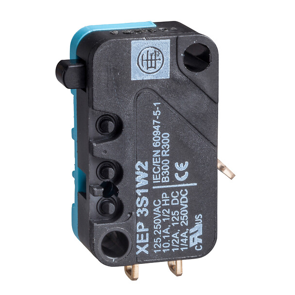
Telemecanique XEP3S1W2 Microswitch: Miniature Limit Switch with Flat Plunger and Snap-Action 1 C/O Contact
Limit confirmation is a fundamental control requirement, and in many machines the most reliable approach is still a mechanical microswitch—especially when the environment or the mechanical arrangement makes non-contact sensing impractical. The Telemecanique XEP3S1W2 microswitch is specified as a miniature limit switch in a special format with a flat plunger head and snap-action contact behavior. When installed with correct force management and travel allowance, microswitches provide deterministic switching with a clear mechanical cause-and-effect relationship.
This technical article explains what the Telemecanique XEP3S1W2 microswitch is, how its contact and mechanical characteristics translate into installation decisions, and how to govern lifecycle performance in high-cycle automation.
Product Identity and Technical Characteristics
The Telemecanique XEP3S1W2 microswitch is specified as a microswitch within the OsiSense XC range, special format, device short name XEP3. It uses a plunger head with linear movement, a flat plunger operator type, and a snap action contact operation. Electrical connection is via solder tags, and contacts are specified as 1 C/O standard (changeover). Contact material is listed as AgNi. Mechanical durability is listed as 20,000,000 cycles. Contact code designation includes AC-15 and DC-13 categories with defined currents at specified voltages.
- Device type: Microswitch, miniature format
- Head/operator: Flat plunger, linear movement, on-end actuation
- Contacts: 1 C/O (changeover), snap action
- Connection: Solder tags
- Mechanical durability: 20,000,000 cycles
These attributes make the Telemecanique XEP3S1W2 microswitch suitable for repeatable end-position confirmation where a physical actuator reliably reaches the switch at every cycle.
Snap Action and C/O Contacts: What the Control System Receives
Snap action is a key performance concept: the switch transitions quickly between states once the actuation point is reached. This supports clean electrical switching and reduces “slow transition” ambiguity in PLC inputs. With 1 C/O contact configuration, designers can select a normally closed or normally open behavior depending on safety philosophy and diagnostic strategy.
In governance terms, C/O contact flexibility should be standardized at the machine level. If one station uses the NC leg as the “healthy” signal and another uses the NO leg, troubleshooting time increases. A clear standard—such as “NC is used for permissive chains” or “NO is used for confirmation”—reduces operational complexity.
Mechanical Integration: Force, Travel, and Overtravel Discipline
Microswitch reliability is driven less by wiring and more by mechanical discipline. The Telemecanique XEP3S1W2 microswitch includes defined values such as maximum force for tripping, minimum release force, and travel-related characteristics including tripping point, maximum differential travel, and minimum overtravel. These parameters should guide cam design and actuator geometry so the switch is actuated positively but not abused. Excessive force or inadequate overtravel allowance can accelerate wear, while insufficient actuation margin can cause intermittent switching at vibration peaks.
A disciplined installation approach includes:
- Ensuring the actuator approaches vertically as specified for the intended approach style.
- Designing a cam profile that meets the tripping point with controlled force.
- Providing consistent overtravel so the switch is not operating at the threshold under vibration.
Electrical Application: Contact Categories and Real Loads
Contact code designations include AC-15 and DC-13 categories with defined currents at specified voltages, which helps engineers align the switch to the intended control circuit class. The best practice is to use the Telemecanique XEP3S1W2 microswitch primarily for control signals (PLC inputs or interposing relays) rather than directly switching loads that create high inrush or heavy inductive stress. This governance choice improves contact life and reduces the risk of welded contacts in demanding duty cycles.
Lifecycle Management: Predictability Through Documentation
Because mechanical durability is specified at 20 million cycles, the device supports high-cycle designs when correctly integrated. Still, the operational outcome depends on inspection discipline. A preventive program should verify bracket tightness, actuator alignment, and consistent approach geometry after mechanical interventions. When a machine is serviced, the most common drift is not the switch itself but the cam or bracket position.
For broader ecosystem references and selection logic, see Telemecanique sensor.
FAQ
- What is the Telemecanique XEP3S1W2 microswitch?
It is a miniature microswitch with a flat plunger head and snap-action 1 C/O contact configuration. - What contact type is provided?
The Telemecanique XEP3S1W2 microswitch provides 1 C/O (changeover) contacts with snap action. - How is it electrically connected?
Electrical connection is specified as solder tags. - What is the mechanical durability rating?
Mechanical durability is specified as 20,000,000 cycles. - What is a typical root cause of microswitch failures?
Poor cam design or misalignment that causes insufficient overtravel or excessive force on the plunger.
When cam geometry, force management, and contact usage are standardized, the Telemecanique XEP3S1W2 microswitch delivers deterministic end-position confirmation with strong lifecycle predictability in industrial automation.