Telemecanique Sensors XMLR040G1P25 Pressure Sensor: 40 bar Monitoring with Analogue and PNP Switching Output
The Telemecanique Sensors XMLR040G1P25 pressure sensor is designed for industrial systems where pressure values up to 40 bar must be continuously monitored while also generating a reliable switching signal for control logic. This reference combines a 4–20 mA analogue output with one PNP switching output, supported by a G 1/4 process connection and an M12 electrical interface. In modern automation, this dual-output architecture enables both diagnostic visibility and deterministic control in a single compact device.
Application Context for 40 bar Systems
Pressure levels around 40 bar are commonly found in reinforced pneumatic systems, hydraulic sub-circuits, and industrial fluid handling installations. In these environments, performance stability depends on maintaining pressure within a defined operating window. The Telemecanique Sensors XMLR040G1P25 pressure sensor provides real-time analogue data for trend analysis while simultaneously delivering a discrete switching signal for permissive control.
For example, in clamping or forming applications, the analogue signal can be used to confirm pressure build-up speed and steady-state value, while the PNP output ensures that a machine cycle only begins once the required threshold is reached.
Telemecanique Sensors XMLR040G1P25 Technical Characteristics Relevant to Integration
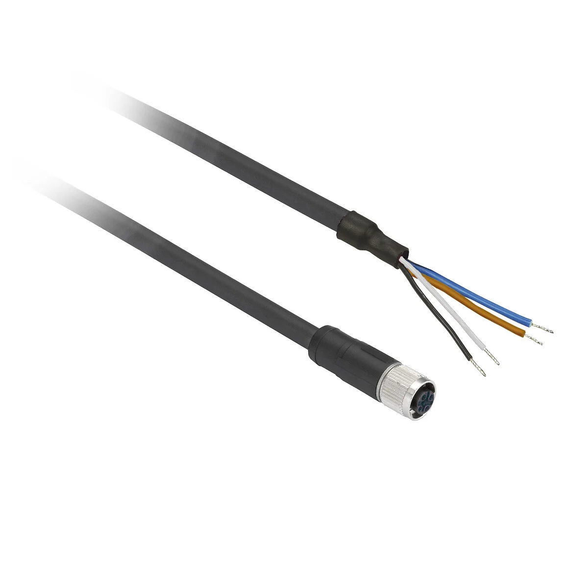
This model is specified as part of the XMLR electronic pressure sensor family, offering a 40 bar measurement range and industrial-standard 4–20 mA output. The additional PNP switching output allows independent configuration of a pressure setpoint. The G 1/4 threaded port simplifies mechanical integration into standard manifolds, and the M12 connector supports consistent field wiring practices.
By integrating both analogue and switching functionality, the Telemecanique Sensors XMLR040G1P25 pressure sensor can reduce panel complexity and streamline wiring.
Telemecanique Sensors XMLR040G1P25 Installation Considerations
To ensure measurement accuracy, install the sensor at a tapping point that reflects true process pressure rather than transient spikes. Avoid immediate proximity to fast-acting valves if pulsation is not part of the measurement objective. Proper sealing of the G 1/4 port prevents micro-leaks that may cause slow pressure decay under load.
- Keep the pressure port free from contamination during installation.
- Use stable mechanical mounting to prevent stress on the housing.
- Route analogue wiring separately from high-power cables where possible.
Commissioning and Calibration Checks
During commissioning, confirm that the analogue output scales correctly within the PLC. Compare the sensor value with a calibrated reference gauge at multiple points. Adjust the switching threshold to allow operational margin above normal pressure ripple. The Telemecanique Sensors XMLR040G1P25 pressure sensor should exhibit repeatable switching behavior across multiple cycles.
If switching instability appears, evaluate process pulsation or regulator fluctuation before replacing the sensor.
Telemecanique Sensors XMLR040G1P25 Operational Benefits
Continuous data from the analogue output supports predictive maintenance. A gradual increase in pressure recovery time may indicate restriction, while a decline in peak value may indicate leakage. The switching output maintains sequence integrity even if the analogue value is used primarily for monitoring.
For related product families, visit Telemecanique sensör.
Telemecanique Sensors XMLR040G1P25 FAQ
1) What is Telemecanique Sensors XMLR040G1P25?
The Telemecanique Sensors XMLR040G1P25 pressure sensor is an electronic transmitter with analogue and PNP switching outputs.
2) What is the pressure rating?
It is specified for applications up to 40 bar.
3) What outputs are available?
It provides a 4–20 mA analogue output and one PNP switching output.
4) What connection standards are used?
It uses a G 1/4 process port and an M12 electrical connector.
5) What causes unstable readings?
Pulsation, poor grounding, or incorrect setpoint selection are common causes.