Telemecanique Sensors XMLP025BC21F Pressure Transmitter: 0–25 bar 4–20 mA Monitoring with DIN 43650 Connection
The Telemecanique Sensors XMLP025BC21F pressure transmitter targets industrial systems that need continuous pressure visibility in the 0–25 bar range. That band is common in pneumatic utilities, process water, and auxiliary hydraulic lines where pressure changes directly influence machine behavior. When the goal is not merely to detect “pressure present,” but to understand whether pressure is stable, rising, or decaying, a transmitter is the more informative instrument.
What XMLP025BC21F Is Referenced To Include
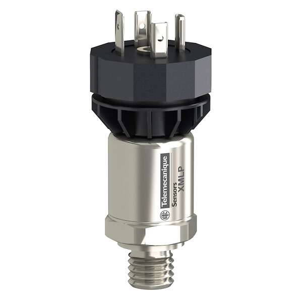
The Telemecanique Sensors XMLP025BC21F pressure transmitter is referenced with a 0–25 bar range, a 4–20 mA two-wire analog output, a G 1/4A male process connection, and an electrical connection style commonly listed as EN 175301-803-A / DIN 43650 (3-pin). These characteristics influence integration: the analog loop supports robust transmission, while the DIN-style connector supports straightforward field wiring where that standard is already used.
Telemecanique Sensors XMLP025BC21F Why 0–25 bar Is a Useful “Operations” Range
In many plants, 0–25 bar is the zone where performance issues first become visible. Pressure losses at this level can produce slow actuators, weak clamping, inconsistent spraying, or unstable valve behavior. Tracking the value continuously allows teams to define meaningful alarms: not only “too low,” but “dropping faster than normal,” which is often the earliest indicator of leakage.
Using the Telemecanique Sensors XMLP025BC21F pressure transmitter as a trend source also helps distinguish between regulator drift and demand spikes. Without a trend, both look like random faults.
Installation: Where You Mount It Defines What You Learn
Continuous measurement is only valuable if the sensing point reflects the real process condition. Avoid mounting immediately after fast-switching valves that create pressure ripple. If pulsation is unavoidable, consider a location with calmer flow dynamics or use suitable damping strategies. Good placement reduces noise and improves the usefulness of trend data.
Mechanically, keep the process port clean during installation and use appropriate sealing practice for the fitting strategy. Electrically, keep analog wiring away from high-power cabling and confirm the PLC input is configured for 4–20 mA. Many commissioning issues are not device-related; they are configuration mismatches.
Commissioning: Make the PLC Value Trustworthy
Commissioning is successful when the displayed value matches reality and remains stable under normal operation. Validate against a reference gauge. Then run the machine and observe the signal during real cycles. If you see rapid fluctuations, investigate pulsation sources and cable routing. If you see slow drift, look at temperature influence and process stability.
When properly commissioned, the Telemecanique Sensors XMLP025BC21F pressure transmitter becomes a practical diagnostic tool: it helps maintenance teams decide whether a fault is pneumatic supply, a restriction, a leak, or a machine demand problem.
Operational Use: From Alarms to Insight
Once stable data is available, define alarms that match reality. Instead of one low limit, many sites define a low limit plus a rate-of-change alarm. That catches leaks early. Trend data can also support preventive maintenance: if pressure recovery time increases week over week, pump wear or filter restriction may be developing.
For additional Telemecanique product context, review Telemecanique sensor.
Telemecanique Sensors XMLP025BC21F FAQ
1) What is XMLP025BC21F?
It is a pressure transmitter for continuous measurement in control and monitoring applications.
2) What range is referenced?
It is referenced for 0–25 bar.
3) What output is referenced?
It is referenced with a 4–20 mA two-wire analog output.
4) What connection types are referenced?
It is referenced with a G 1/4A male process port and a DIN 43650 style electrical connector.
5) Why might the signal fluctuate?
Valve pulsation near the sensing point or poor cable routing can introduce instability.