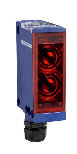
Telemecanique XUX1ARCNT16 Reflex Photoelectric Sensor: Long-Corridor Detection with Relay Output Governance
The Telemecanique XUX1ARCNT16 reflex photoelectric sensor is typically applied where one-sided installation is preferred and where the detection corridor benefits from a reflector-based optical path. Reflex sensing places the sensor on one side of the machine and a reflector on the opposite side; an object is detected when it interrupts the returned beam. This architecture is common in conveyor lanes, pallet detection zones, and machine guarding interfaces—especially when mechanical access is limited on one side.
Confirmed characteristics and what they imply for engineering
Manufacturer datasheet language identifies XUX1ARCNT16 as a photoelectric sensor in the XUX compact 92 × 71 format, using a reflex detection system with a nominal sensing distance of Sn 14 m, and supporting 24…240 VAC/DC supply with terminals. It is also specified with a discrete output function 1 C/O, consistent with relay changeover behavior.
Technical snapshot (for specification sheets)
- Brand + code + type: Telemecanique XUX1ARCNT16 reflex photoelectric sensor
- Detection system: Reflex
- Nominal distance: Sn 14 m
- Supply: 24…240 VAC/DC
- Electrical connection: Screw/terminal style (terminals)
- Output function: 1 C/O (changeover relay logic)
Why relay output matters in mixed-voltage industrial environments
Many plants operate a hybrid environment: modern PLC inputs alongside legacy relay logic, AC-controlled interfaces, or multi-voltage interlocks. A relay-style 1 C/O output can simplify integration where the receiving circuit expects a dry contact or where isolation is desirable. For the Telemecanique XUX1ARCNT16 reflex photoelectric sensor, this can reduce the need for intermediate interface relays in certain architectures—provided the electrical durability and switching rate are aligned with the application duty cycle.
However, relay outputs also require governance. Engineers must consider contact wear when switching high currents or inductive loads. In practice, most automation teams use the relay output to drive PLC inputs or low-energy signaling circuits, then let the PLC control actuators via dedicated outputs. This approach helps preserve relay life and improves maintainability.
Commissioning discipline: reflector alignment is a system requirement
Reflex sensors are not “mount and forget” unless the reflector is treated as part of the system. The Telemecanique XUX1ARCNT16 reflex photoelectric sensor should be aligned to the reflector at the intended operating distance, then verified with the smallest object that must be detected. Alignment should be checked under vibration and temperature variation if the corridor is long. A common reliability pattern is to create an alignment reference: a small notch or index mark on the bracket, plus a quick-check part that can be inserted to confirm switching behavior.
Reflector selection and placement are also critical. If the reflector sits in a high-contamination zone, return signal may degrade over time. Preventive cleaning routines and protective placement (shielding from direct impact) are often more effective than increasing sensitivity to compensate for dirty optics.
Mechanical integration: bracket rigidity and cable governance
Because the sensor corridor can extend to 14 m, small angular errors can lead to large misalignment at the reflector. Even with robust housings, the dominant failure mode can be bracket flex or accidental bumps during maintenance. Use rigid mechanical support, avoid long cantilever mounts, and route cables so they do not apply rotational torque to the sensor body. These actions increase the stability of the Telemecanique XUX1ARCNT16 reflex photoelectric sensor without changing electrical settings.
For standardization across installations, see Telemecanique sensor.
Telemecanique XUX1ARCNT16 FAQ
- What detection system does XUX1ARCNT16 use?
It is specified as a reflex photoelectric sensor. - What is the nominal sensing distance?
The datasheet lists Sn 14 m. - What supply voltage range is supported?
24…240 VAC/DC is specified. - What does “1 C/O” mean in practical wiring?
It indicates a changeover contact (NO/NC behavior available via relay common wiring). - What is the most common real-world cause of reflex sensing issues?
Reflector contamination or bracket misalignment—both should be managed via preventive checks.
Entity recap: The Telemecanique XUX1ARCNT16 reflex photoelectric sensor is a long-corridor reflector-based device with Sn 14 m, 24…240 VAC/DC supply, and 1 C/O relay-style output on terminals, suited for governed industrial detection systems.