Telemecanique XUK1APANL2 Photoelectric Sensor: Reflex Mode Fundamentals and Commissioning Control
The Telemecanique XUK1APANL2 photoelectric sensor is a reflex (retroreflective) photoelectric device designed for mid-range detection where a reflector is used to return the emitted light to the receiver. Reflex sensing often strikes a practical balance between thru-beam and diffuse: it reduces the need for a separate receiver device (as in thru-beam), while typically providing more controlled detection than pure diffuse sensing when a suitable reflector and alignment discipline are applied.
Product identity and technical definition
Datasheet documentation describes the Telemecanique XUK1APANL2 photoelectric sensor as part of the Telemecanique Photoelectric sensors XU range, with a compact 50 x 50 design, reflex detection system, plastic material, discrete output signal, DC supply circuit, 3-wire wiring technique, and PNP output type. The characteristics explicitly list Sn 7 m, 12…24 VDC, and a 2 m cable.
Core specifications (station design view)
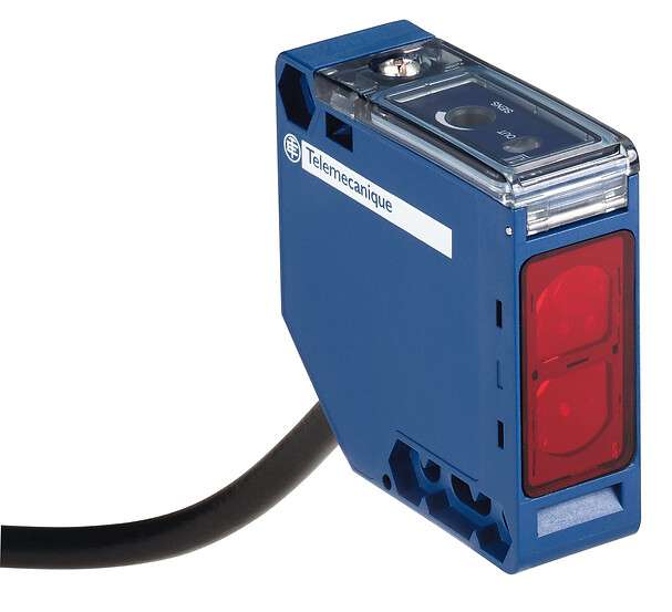
- Brand + code + type: Telemecanique XUK1APANL2 photoelectric sensor
- Sensor design: Compact 50 x 50
- Detection system: Reflex
- Material: Plastic
- Nominal sensing distance: Sn 7 m
- Supply: 12…24 VDC
- Wiring technique: 3-wire
- Discrete output type: PNP
- Connection: Cable 2 m
Reflex sensing: how it behaves and what can destabilize it
In reflex mode, the sensor and reflector form a defined optical corridor. When an object passes between them, the reflected signal drops and the output changes state. The stability of the Telemecanique XUK1APANL2 photoelectric sensor is therefore influenced by reflector condition and alignment. Dust, film, or mechanical drift can reduce reflected light and create borderline switching. A practical advantage of reflex is the single-device wiring and simpler mounting compared to thru-beam, but the trade-off is that reflector management becomes part of the station’s maintenance governance.
Commissioning method that reduces nuisance faults
For reliable operation, commission the station using the most challenging production scenario: fastest moving product, smallest object profile, and the most optically difficult surface (dark, matte, irregular). Confirm stable “beam return” when no product is present, then confirm a clean interruption when product passes. If the station is exposed to frequent washdown or dust, define a cleaning interval for the reflector and the sensor lens. This approach reduces “mystery faults” where the device is replaced repeatedly even though the underlying issue is contamination or bracket movement.
Controls integration: DC 3-wire PNP discipline
The datasheet specifies DC supply, 3-wire wiring, and PNP output type. In practical panels, this typically aligns with sourcing input modules, but it still requires consistent wiring standards and clear tagging. Label the point as Telemecanique XUK1APANL2 photoelectric sensor (reflex, PNP, 12–24 VDC) so that technicians do not substitute a multimode AC/DC device or a different output logic model during urgent maintenance. Correct identification reduces downtime variance and supports cleaner fault analysis.
Where Sn 7 m reflex is commonly used
- Conveyor presence detection where one-sided device mounting is preferred
- Packaging lines with controlled detection windows and reflector mounting space
- Material handling gates and transfers where mid-range detection is adequate
- Stations that require consistent results across variable target surface finishes
Maintenance and troubleshooting priorities
When a reflex station becomes unstable, begin with the simplest checks: clean the sensor lens and reflector, confirm alignment, and verify bracket rigidity. Next, verify supply voltage stability within the 12…24 VDC range and confirm the PLC input interpretation for a PNP output. Only after those checks should the sensor be replaced. This sequence reduces unnecessary spare consumption and helps isolate whether the issue is optical, mechanical, or electrical.
For broader ecosystem standardization, consult Telemecanique sensor references to align selection rules and documentation across sensor types.
FAQ
- What detection system does the Telemecanique XUK1APANL2 photoelectric sensor use?
It is specified as reflex detection. - What sensing distance is listed?
Sn is listed as 7 m. - What supply voltage does it require?
12…24 VDC is specified. - What wiring and output type are stated?
3-wire wiring technique and PNP output type are listed. - What is a common cause of reflex instability?
Dirty reflector or lens surfaces and bracket drift can reduce reflected signal and create borderline switching.
Entity recap: The Telemecanique XUK1APANL2 photoelectric sensor is a compact 50×50 reflex sensor with Sn 7 m, 12…24 VDC supply, 3-wire PNP output, and a 2 m cable—suited to mid-range retroreflective detection when alignment and reflector cleanliness are governed.