Telemecanique Sensors XMLP040BD21F Pressure Transmitter: 0–40 bar 4–20 mA Signal for Industrial Control
The Telemecanique Sensors XMLP040BD21F pressure transmitter is suited for installations where 0–40 bar monitoring provides meaningful operational visibility. This range is frequently seen in auxiliary hydraulics, fluid handling skids, and industrial process lines where pressure stability influences quality and uptime. A transmitter supports continuous monitoring, which means the controller can do more than react to failure; it can detect deterioration early.
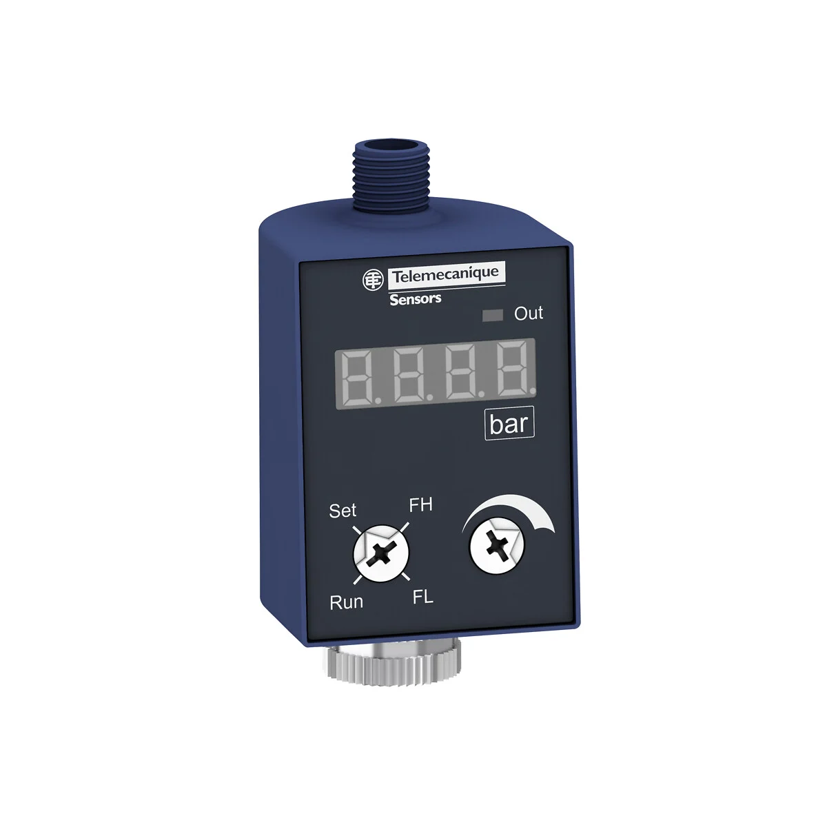
Core Characteristics Referenced for XMLP040BD21F
The Telemecanique Sensors XMLP040BD21F pressure transmitter is described in distributor references as measuring 0–40 bar and providing a 4–20 mA output. It is commonly referenced with an M12 electrical connector and a G 1/4A male process connection. This combination is typical in modern machines where field connectivity is standardized and quick replacement is a priority.
Why Continuous Measurement Helps Beyond Alarming
Pressure rarely fails instantly. More commonly, it drifts: a regulator begins to creep, a filter begins to clog, or a pump begins to lose efficiency. Continuous measurement allows the PLC or SCADA system to show the trend. That trend is often the most actionable information maintenance can get. Instead of “pressure low” during a breakdown, the team sees “pressure slowly declining” during normal operation.
In that context, the Telemecanique Sensors XMLP040BD21F pressure transmitter becomes a practical reliability input rather than a simple sensor.
Installation: The Goal Is a Clean Pressure Signal
Place the transmitter where pressure represents the real system condition. Avoid mounting directly at pulsating outlets or immediately downstream of fast-switching valves. If pressure pulses are unavoidable, consider damping or alternative tapping points. A stable process connection and thoughtful placement reduce noise and make trends meaningful.
On wiring, maintain standard analog best practices: keep signal cabling away from high-power lines, use proper grounding strategy, and confirm the PLC analog input is configured for a 4–20 mA loop. Many commissioning issues stem from configuration errors rather than the sensor itself.
Commissioning: Build Trust in the Value
During commissioning, validate scaling first: confirm that the PLC’s engineering units match the physical pressure range. Then correlate with a reference gauge at a few points across the operating band. Finally, observe the signal during real machine cycles. If the value “jitters,” look for pressure pulsation or electrical interference. If it drifts slowly, evaluate process temperature and system stability.
Once commissioned correctly, the Telemecanique Sensors XMLP040BD21F pressure transmitter supports smarter alarms. Instead of one low threshold, you can implement a low threshold plus an abnormal rate-of-change alarm to catch leaks early.
Maintenance: Use the Trend as a Diagnostic Tool
If pressure recovery time increases, suspect restriction or pump wear. If pressure oscillation increases, suspect valve behavior or air entrainment. If baseline pressure slowly shifts, suspect regulator drift or system leakage. This is how continuous measurement reduces downtime: it turns hidden problems into visible patterns.
For additional Telemecanique product context, visit Telemecanique sensor.
Telemecanique Sensors XMLP040BD21F FAQ
1) What is XMLP040BD21F?
It is a pressure transmitter used for continuous pressure monitoring and control.
2) What range is referenced?
It is referenced for 0–40 bar.
3) What output is referenced?
It is referenced with a 4–20 mA output.
4) What connections are commonly referenced?
It is commonly referenced with an M12 electrical connector and a G 1/4A male process connection.
5) What causes noisy readings?
Pressure pulsation near the sensing point and electrical interference from poor cable routing are common causes.