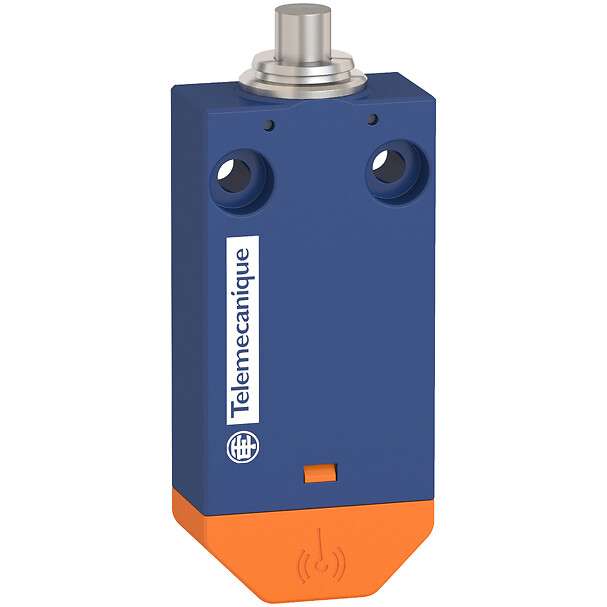
Telemecanique Sensors XCMW110 Wireless / Batteryless Limit Switch: Practical Guide for Cable-Free Machine Detection
The Telemecanique Sensors XCMW110 limit switch is part of the XC Wireless concept: a wireless and batteryless switching solution designed for detection points where cabling is difficult, costly, or undesirable. Instead of relying on a conventional wired contact block with a hardwired input, the XCMW approach focuses on sending a switching event over radio, reducing cable routing constraints on machines with moving sections, rotating parts, or frequently reconfigured modules. Telemecanique Sensors positions the XCMW range as a way to simplify machine communication when cable management becomes a bottleneck. (Source: RS Online product description for XCMW110, and Telemecanique Sensors reference page)
What “Wireless and Batteryless” Means in Real Installations
In day-to-day automation work, “wireless” is only useful if maintenance teams can trust signal consistency. “Batteryless” is only valuable if it eliminates recurring service tasks rather than introducing uncertainty. The XCMW110 is presented as a wireless/batteryless limit switch solution within the XCMW range. (Telemecanique Sensors reference page for XCMW110)
The most important practical takeaway is that commissioning must treat radio performance as part of the engineering scope. Mechanical mounting, cabinet materials, and obstacles can change radio behavior. The XCMW110 documentation set includes installation and mounting considerations, including attention to signal attenuation when mounting in or near metal structures.
Mounting: Clearance, Fixings, and Avoiding “Hidden” Radio Problems
Limit switches are usually mounted by thinking about mechanical approach and actuation. With XCMW110, you also need to think about the RF path to the receiver. The XCMW110 datasheet includes mounting and clearance guidance and explicitly discusses attenuation effects depending on materials, with examples such as metal structures and glass windows. That is valuable because a switch that works perfectly on an open bench can become unreliable once enclosed by a metal cabinet or placed behind structural members. (Mouser XCMW110 document: mounting/clearance and attenuation tables)
From an operational standpoint, treat this as a two-step validation:
- Mechanical validation: confirm the actuator is consistently triggered at the intended machine position.
- Radio validation: confirm the receiver sees stable events under real machine conditions, including doors closed, guards in place, and neighboring equipment running.
System Integration: Receiver Compatibility and I/O Planning
The XCMW110 product page notes compatibility with programmable receiver solutions as related items, emphasizing that the switch is part of a system rather than a standalone wired device. That system orientation impacts how you design the control panel: instead of dedicating a standard digital input per switch, you plan for the receiver’s outputs and how they map into PLC logic. (Telemecanique Sensors XCMW110 reference page, related products)
For maintenance teams, system-based design can simplify replacement if the receiver mapping is documented clearly. A practical best practice is to label the receiver I/O to match the machine function (for example, “Guard A Closed,” “Transfer Home,” “Lift Upper Stop”) rather than just “Input 1,” “Input 2.”
Commissioning Checklist for Reliable Operation
- Confirm physical actuation repeatability: the moving part must hit the switch consistently without side loading or snagging.
- Validate with machine guards in place: metal panels can change radio behavior; test in the final configuration.
- Check for dynamic obstacles: moving carriages, forklifts, and cranes can create intermittent attenuation; observe behavior during normal traffic.
- Document receiver mapping: ensure the PLC tag list matches the receiver outputs and the machine function.
For a broader view of compatible sensing solutions and standardization across projects, visit Telemecanique sensor.
FAQ
1) What is the core concept of XCMW110?
It is presented as a wireless and batteryless limit switch solution in the XCMW range. (Telemecanique Sensors product reference)
2) Why do mounting materials matter?
The documentation highlights signal attenuation depending on materials such as metal structures, so mounting can affect RF performance. (Mouser XCMW110 document)
3) Is XCMW110 meant to work alone?
The product page indicates compatibility with receiver products, showing it is part of a wireless system. (Telemecanique Sensors XCMW110 reference)
4) What is a common commissioning mistake?
Testing radio performance only on an open bench and not with the final guards/panels installed is a frequent cause of later instability. (Supported by attenuation guidance in the XCMW110 documentation)
5) Where does XCMW110 fit best?
It is positioned for machines where cabling is difficult, expensive, or unwanted, and where maintenance reduction is valuable. (RS product description and Telemecanique Sensors reference)