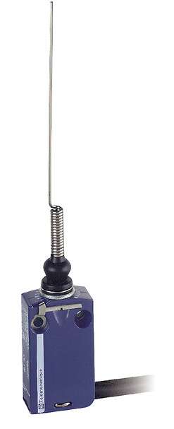
Telemecanique Sensors XCMD2106L1 Limit Switch: Miniature Modular Metal Switch for Space-Constrained Automation
The Telemecanique Sensors XCMD2106L1 limit switch is part of the XC family in a miniature modular metal format intended for machine builders who need dependable mechanical switching in a compact footprint. In many automation designs, there are detection points where a standard-size limit switch cannot be placed without redesigning guards or frames. A miniature form factor allows the switch to be positioned close to the moving element, reducing the need for linkages and improving mechanical clarity during maintenance.
In the product data sheet, Telemecanique Sensors XCMD2106L1 is shown with a 2-pole NC + NO snap-action wiring diagram and installation guidance for mounting and cable sweep, emphasizing practical deployment in real machine layouts.
Telemecanique Sensors XCMD2106L1 Miniature Format and What It Enables
Miniature limit switches are typically selected for three reasons:
- Space constraints: compact stations, small actuators, or dense assemblies where standard bodies interfere with motion.
- Short mechanical paths: direct actuation without long linkages can reduce tolerance stack-up.
- Maintenance accessibility: a smaller switch can often be positioned where technicians can view the actuation point clearly.
For Telemecanique Sensors XCMD2106L1, the documentation highlights mounting details and positioning considerations for the connecting cable. This is important because miniature switches are often placed close to moving parts; cable routing must be planned so repeated machine motion does not fatigue the cable or cause snagging.
Telemecanique Sensors XCMD2106L1 Wiring Concept and Control Integration
The datasheet provides a clear reference: 2-pole NC + NO snap action. In typical control logic, this allows designers to implement either fail-aware logic using NC (for example, monitoring continuity) or event-based logic using NO, depending on how the PLC program is structured. Snap action supports clean state changes, which is especially valuable when the actuator moves slowly through the switching zone.
The wiring diagram also includes conductor color references (as shown in the documentation). For commissioning teams, this reduces ambiguity and supports consistent field practices when replacing a switch quickly during downtime.
Cable and Mounting Considerations
Telemecanique Sensors XCMD2106L1 documentation includes a dimension note for the external cable diameter and shows mounting guidance such as “recommended” vs “to be avoided” for cable sweep. These details matter in practice because cable bend radius and repeated flexing are common failure sources in high-cycle automation equipment. Proper routing protects both electrical integrity and mechanical uptime.
The data sheet also references mounting holes and countersink dimensions, which is useful for fixture design and retrofit work when technicians need to install the switch on a small bracket or a machined plate.
Actuation Style and Practical Use
The technical description section indicates switch actuation by a moving part and includes a functional diagram describing closed/open/tripping/resetting behavior. In practical troubleshooting, this is valuable because it aligns the mechanical motion (what the technician sees) with the electrical behavior (what the PLC reads). When a machine reports intermittent position confirmation, the functional diagram helps teams determine whether the issue is insufficient travel, poor return, or mechanical interference.
Operational Discipline for Reliability
- Protect the cable path: keep the cable clear of pinch points and high-abrasion edges.
- Ensure stable mounting: miniature switches still require rigid brackets; flex introduces signal inconsistency.
- Confirm adequate actuation travel: the mechanism should cross the snap region confidently, not hover near it.
To explore compatible products and maintain selection consistency across machine families, see Telemecanique sensör.
Telemecanique Sensors XCMD2106L1 FAQ
1) What contact arrangement is shown for XCMD2106L1?
The documentation shows a 2-pole NC + NO snap-action wiring diagram.
2) Does the documentation include mounting guidance?
Yes, it includes mounting and clearance guidance, including cable sweep recommendations.
3) Why is cable sweep guidance important?
Because repeated flexing or tight bends can fatigue the cable over time, especially near moving parts.
4) Are mounting hole details provided?
Yes, the dimensions section lists fixing hole details and related mounting information.
5) What does the functional diagram help with?
It helps relate mechanical travel to electrical states such as closed, open, tripping, and resetting.