Telemecanique Sensors XCJ103C Limit Switch: Technical Guide for Steel Roller Plunger Vertical Actuation
The Telemecanique Sensors XCJ103C limit switch is designed for dependable position feedback in light to medium duty industrial automation. Built around a fixed body architecture and a plunger head, this device uses a spring return roller plunger in stainless steel to detect mechanical movement at the end of travel. In practical terms, the XCJ103C translates a physical contact event—like a moving carriage reaching a stop—into a clean electrical change of state that control systems can read with confidence.
Because it belongs to the OsiSense XC Basic family, the Telemecanique Sensors XCJ103C limit switch is commonly evaluated as a compact, straightforward solution when engineers need simple end-of-stroke confirmation without complex electronics. It uses a snap-action contact mechanism and is typically installed by the body, allowing consistent mounting geometry in panels, machine frames, and compact guarding structures.
Core Identity and What Makes XCJ103C Distinct
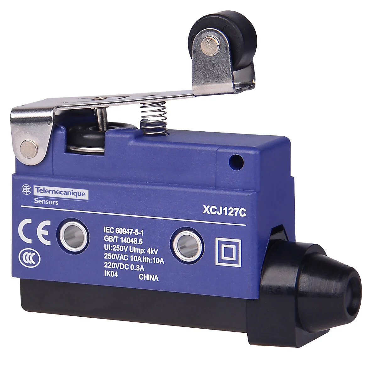
While many limit switches share similar electrical behavior, the distinguishing trait of the Telemecanique Sensors XCJ103C limit switch is its actuation approach: vertical actuation with on-end switching through a steel roller plunger. The roller reduces friction and helps the actuator tolerate repeated contact from cams or moving machine parts. That rolling contact can improve repeatability in setups where a sliding plunger might wear faster or produce inconsistent engagement.
Telemecanique Sensors XCJ103C Key Technical Characteristics
- Product type: Limit switch for light to medium duty applications
- Body concept: Fixed body, installed by the body for stable alignment
- Head and motion: Plunger head with linear operating head movement
- Actuator: Spring return roller plunger (stainless steel)
- Switch actuation: On end
- Approach type: Traverse approach, 1 direction
- Contact behavior: Snap action (fast transition to reduce contact chatter)
- Electrical connection: Screw-clamp terminals
- Cable entry: Flexible rubber cable gland (typical outer diameter 8.5–10.5 mm)
- Contact code designation: A300 (AC), R300 (DC) class references used for rating context
- Protection: IP40 class for dust protection suitable for enclosed or controlled environments
Where the Telemecanique Sensors XCJ103C Fits in Industrial Systems
The Telemecanique Sensors XCJ103C limit switch is generally selected when a machine needs deterministic end-position confirmation. Typical examples include:
- Conveyor diverters and stops where a moving element reaches a mechanical end point
- Packaging machinery where a slide, clamp, or pusher needs a “home” or “end” signal
- General machine tools for axis limit confirmation in guarded or enclosed zones
- Light material handling equipment where compact form and simple wiring are priorities
If your application requires broader environmental sealing (for washdown or heavy contamination), IP-rated alternatives might be more appropriate. However, in many enclosed cabinet-adjacent mechanisms, the Telemecanique Sensors XCJ103C limit switch provides a balanced mix of simplicity and dependable switching.
Mounting and Actuation Engineering Notes
Mechanical alignment is the difference between a limit switch that “works in the lab” and one that remains stable in production. With the XCJ103C, focus on these principles:
- Ensure consistent end contact: The roller plunger should be engaged predictably by a cam or striker at the intended trip point.
- Avoid side loading: Although the roller helps, excessive lateral forces can accelerate wear or create inconsistent travel.
- Respect travel margins: Leave a small safety margin so minor vibration does not cause intermittent actuation.
- Use secure body mounting: Because mounting is “by the body,” use a rigid surface and hardware that will not loosen under vibration.
For engineers building a standardized sensor portfolio, it is also useful to keep a consistent sourcing path for related components. If you are mapping a broader sensor ecosystem, you can review additional options under Telemecanique sensor to maintain consistency across installations.
Electrical Integration and Wiring Practices
The Telemecanique Sensors XCJ103C limit switch is typically integrated into discrete inputs of PLCs or safety relays depending on the architecture. Screw-clamp terminals support practical field wiring and serviceability. In wiring design, emphasize:
- Clean cable routing: Reduce mechanical pull on the gland and prevent cable fatigue at moving joints.
- Noise awareness: Route signal wiring away from high-current motor cables when possible.
- Input filtering: If your PLC supports input debounce or filtering, apply a conservative filter to suppress vibration-induced toggling.
Reliability, Inspection, and Maintenance
In routine preventive maintenance, treat the Telemecanique Sensors XCJ103C limit switch as both an electrical and mechanical component. Inspect the actuator for wear, confirm mounting integrity, and check that the actuation point still matches the intended mechanical position. A quick functional test—moving the cam slowly to confirm repeatable switching—often detects issues before downtime occurs.
Telemecanique Sensors XCJ103C FAQ
1) What actuator style does the XCJ103C use?
The XCJ103C uses a spring return stainless-steel roller plunger designed for vertical, on-end actuation.
2) Is the XCJ103C suitable for heavy-duty outdoor exposure?
It is typically used in controlled or enclosed environments due to its IP40 protection class. For harsher conditions, consider higher IP-rated alternatives.
3) What kind of electrical connection is provided?
The device uses screw-clamp terminals, supporting straightforward installation and easier servicing.
4) Why choose a roller plunger instead of a plain plunger?
A roller plunger can reduce friction and wear at the contact point, improving repeatability in cam-driven mechanisms.
5) What is a common cause of inconsistent switching in limit switches?
Misalignment, side loading, and insufficient travel margin are frequent causes. Correct mounting geometry typically resolves the issue.
. These variations help technical teams standardize terminology across maintenance, procurement, and engineering records.