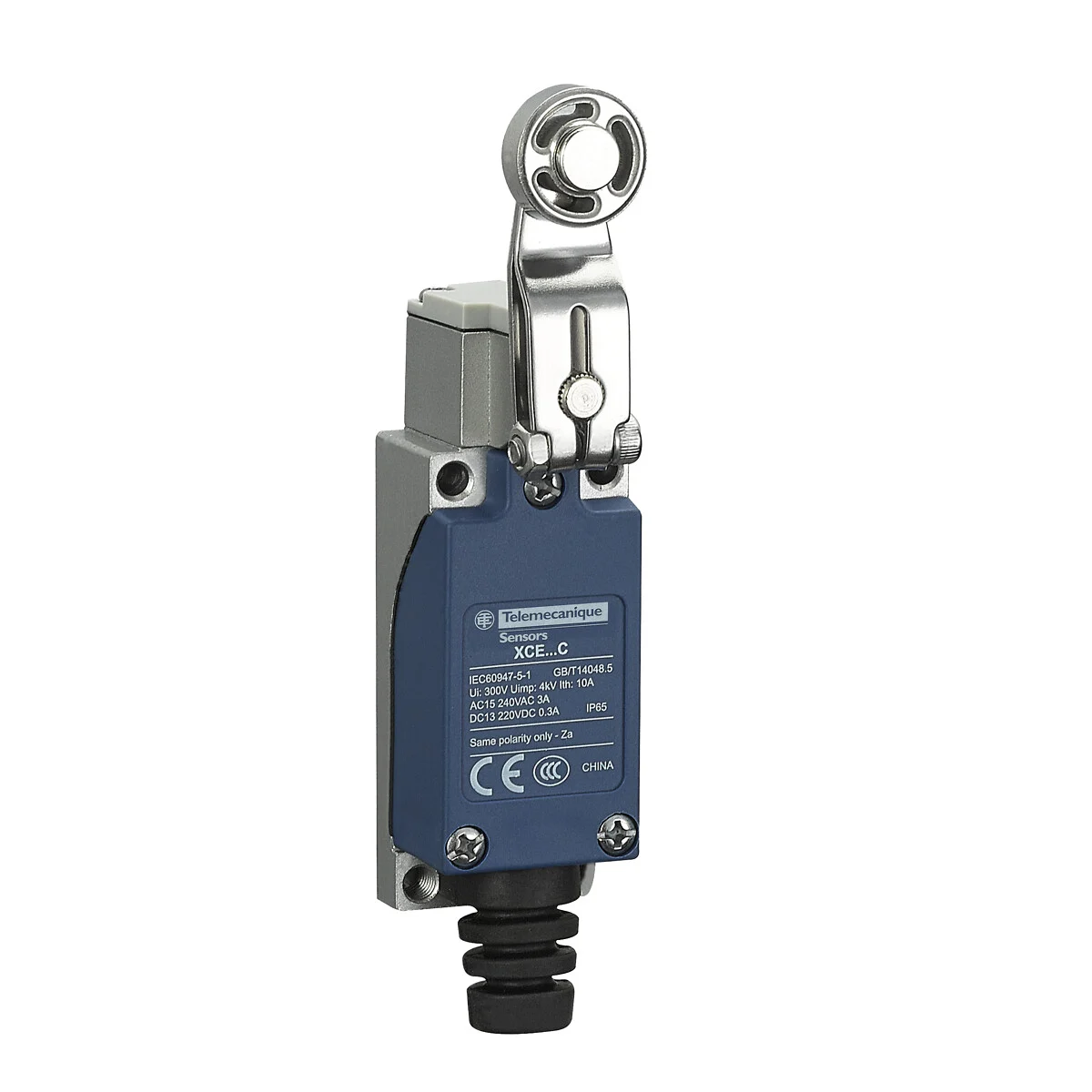
Telemecanique Sensors XCE118C Limit Switch: Thermoplastic Roller Lever for Cam-Driven Detection
The Telemecanique Sensors XCE118C limit switch is designed for applications where a cam, ramp, or guiding surface engages a roller lever to create a repeatable switching point. As an OsiSense XC Basic series limit switch for medium-duty use, the XCE118C combines a rotary head with a spring return thermoplastic roller lever, enabling efficient lateral detection on moving mechanisms without requiring a direct plunger press.
Recognizable Search Phrases and Variations
Common engineering and procurement queries include Telemecanique Sensors XCE118C limit switch, Telemecanique XCE118C limit switch, and Telemecanique Sensors XCE118C roller lever limit switch. These variations map to the same product identity and help align the “brand + product code + product type” convention used in technical catalogs and maintenance lists.
Technical Specifications Snapshot (Telemecanique Sensors XCE118C)
- Range / Series: OsiSense XC, Basic
- Product type: Limit switch; Application: Medium duty
- Body / Head: Fixed body; rotary head
- Actuator: Spring return roller lever (thermoplastic)
- Switch actuation: By 30° cam
- Approach: Lateral approach, 2 directions
- Electrical connection: Screw-clamp terminals (1 x 1.5 mm²)
- Cable entry: Flexible rubber cable gland; cable OD 6–9 mm
- Contact operation: Snap action
- Operating rate: 120 cycles/min
- IP rating: IP65 (IEC 60529)
- Ratings: A300 (AC 240 V, Ie 3 A, Ithe 10 A) and R300 (DC 220 V, Ie 0.3 A) per IEC 60947-5-1
Telemecanique Sensors XCE118C Why a Roller Lever Matters in Automation Design
In a cam-driven mechanism, contact friction and wear are design realities. The roller lever on the Telemecanique Sensors XCE118C limit switch can reduce sliding friction compared with flat lever contact, because the roller rotates as the cam passes. The specification that actuation is “by 30° cam” also supports predictable switching geometry: the cam angle and lever travel relationship becomes part of the repeatability profile.
From an operational excellence standpoint, repeatable detection reduces nuisance stops and supports stable cycle timing. It also simplifies troubleshooting, because the mechanical approach is visible and testable without requiring complex instrumentation.
Telemecanique Sensors XCE118C Mounting and Alignment Guidance
When installing a Telemecanique XCE118C limit switch, the most critical governance point is alignment between the cam path and the roller lever. The switch supports lateral approach in two directions, which is useful on bidirectional motion or when the cam can approach from either side. Proper mounting should ensure the cam engages the lever within the intended travel range and does not over-travel, which can accelerate mechanical fatigue.
Electrical Integration and Signal Quality
XCE118C uses screw-clamp terminals and a sealed cable gland to help preserve IP performance. In PLC integrations, a roller lever limit switch is still a mechanical contact device, so high-speed counters or very high-frequency detection may require input filtering or software debouncing. The stated operating rate of 120 cycles per minute provides a practical reference for typical machine cycles. :
When Telemecanique Sensors XCE118C Is the Right Selection
Choose Telemecanique Sensors XCE118C limit switch when your application uses a cam and you want a robust, repeatable lateral detection point with reduced friction at the actuation interface. If your approach is strictly vertical or end-on pressing, a plunger head may be the more direct mechanical match. For additional Telemecanique product ecosystem context, visit Telemecanique sensor.
FAQ (Telemecanique Sensors XCE118C)
- What makes XCE118C different from a plunger limit switch?
It uses a rotary head and roller lever and is intended for cam-driven lateral actuation rather than end-on pressing. - How is the switch actuated?
The datasheet states actuation “by 30° cam,” supporting predictable cam geometry. - Can it detect motion from both sides?
Yes, it is specified for lateral approach in two directions. - What is the ingress protection rating?
IP65 per IEC 60529 with correct installation. - What wiring interface is provided?
Screw-clamp terminals (1 x 1.5 mm²) and a 6–9 mm cable gland entry.